
How PCB vias impact the signal transmission
Via is one of the most important parts of multilayer PCB board. The drilling cost usually accounts for 30% to 40% of PCB board cost.Simply put, every hole in the PCB can be called a through hole.
Parasitic capacitance through holes
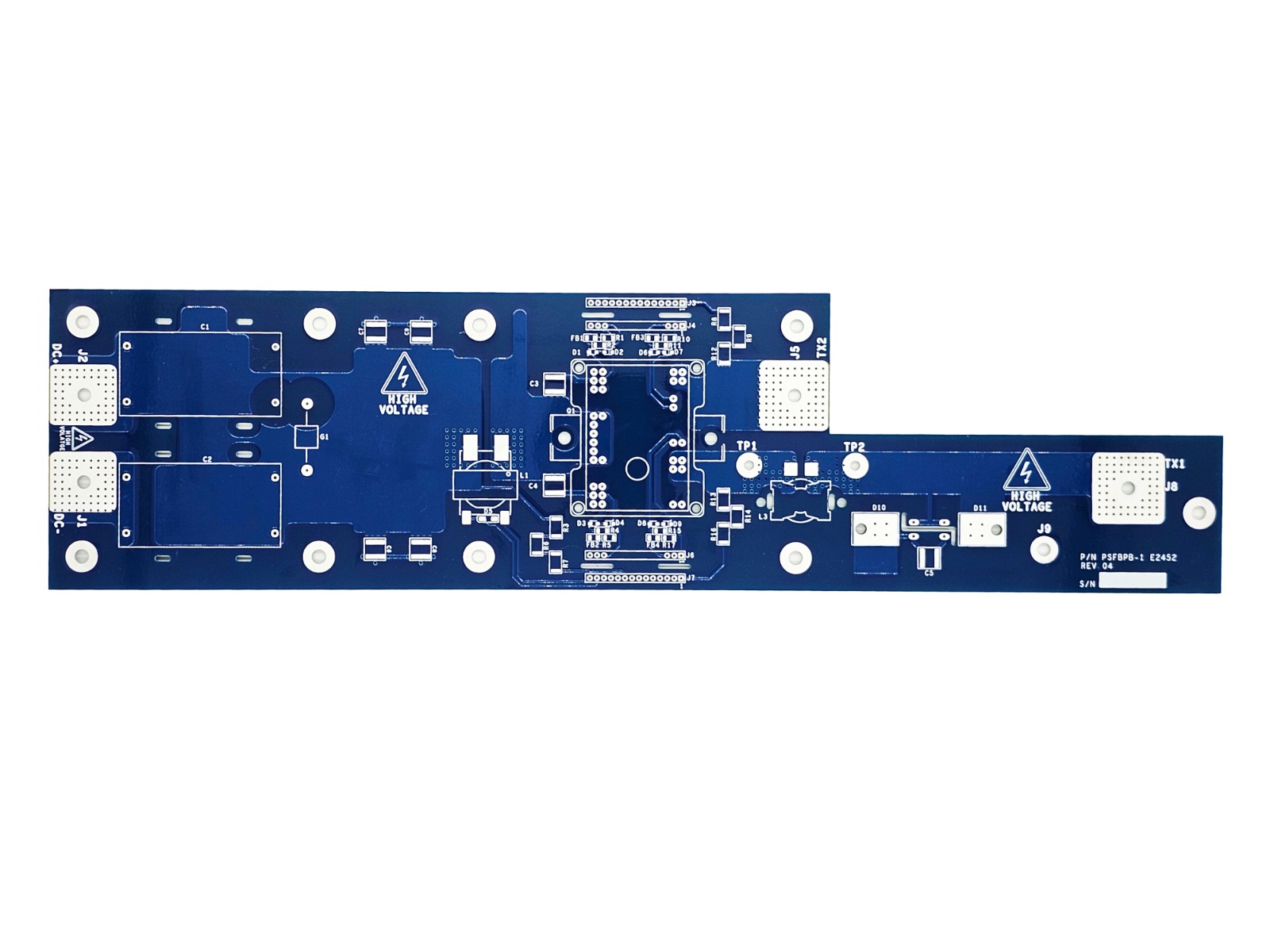
If the diameter of the hole is D2, the diameter of the hole pad is D1, the thickness of PCB board is T, and the dielectric constant is ,, the parasitic capacitance of the hole is approximately C=1.41TDTD1/(D2-D1) which will cause an increase in signal time and decrease circuit speed.For example, for a PCB board with a thickness of 50Mil, the parasitic capacitance of the board with an internal diameter of 10Mil, a pad diameter of 20Mil, and a distance of 32Mil from the ground copper zone can be approximated by the above formula: C=1.41x4.4x0.050x0.020/(0.032-0.020)=0.517pF.From these values, it can be seen that, although the effectiveness of rising delay due to parasitic capacitance of a single hole is not obvious, designers should consider using multiple holes for interlayer switching.
Parasitic inductance through holes
Similarly, parasitic capacitance exists as well as parasitic inductance. In the design of high-speed digital circuits, parasitic inductance is more harmful than parasitic capacitance.Its parasitic series inductance will weaken the contribution of bypass capacitance and reduce the filtering effect of the whole power supply system.We can simply calculate the parasitic inductance of a through hole approximation using the following formula: L = 5.08 h[ln(4 h/d)+1], where L denotes the through hole length, and d is the diameter of the central borehole.From the formula, it can be seen that the diameter of the hole has little effect on the inductance, but the length of the hole has the greatest effect on the inductance.Using the above example, the inductance of the perforation can be calculated as: L = 5.08 x 0.050 [ln(4 x 0.050/0.010) + 1] = 1.015 nH.If the rise time of the signal is 1 ns, the equivalent impedance is XL=πL/T10-90=3.19。.This impedance can no longer be ignored at high frequencies, especially if the by-pass capacitance passes through two holes when connecting the power supply layer to the stratum, thus multiplying the parasitic inductance.
Design of Passage in High Speed PCB
Through the analysis of the parasitic characteristics of the holes above, we can see that in high-speed PCB design, seemingly simple holes often bring a lot of negative effects to the circuit design.In order to minimize the adverse effects of parasitization, the following can be done in the design:
1. Choose reasonable size through hole considering cost and signal quality.For example, 10/20Mil (drilling/welding pad) is a good choice for 6-10-layer memory module PCB designs, and 8/18Mil is also a good choice for small boards with high density.Under current technical conditions, it is difficult to use a smaller through hole.For power or ground holes, consider using larger sizes to reduce impedance.
2. The two formulas discussed above can be concluded that the use of thinner PCB plates is beneficial to reduce the two parasitic parameters of the perforation.
3. The pins of the power supply and ground should be perforated close to each other. The shorter the lead between the holes and the pins, the better, because they will increase the inductance.At the same time, the power supply and ground leads should be as thick as possible to reduce impedance.
PCB board signal line as far as possible not to change the layer, that is, try not to use unnecessary holes.
5. Place some grounding holes near the holes in the signal exchange layer to provide the nearest loop for the signal.It is even possible to place a large number of redundant grounding holes on the PCB board.Of course, design needs to be flexible.The perforation model discussed above is that each layer has a welding pad, and sometimes we can reduce or even remove the welding pad of some layers.In addition to moving the hole position, we can consider reducing the size of the pad in the copper layer.
 Circuit Board Assembly Services for OEM Plant Production
 How PCB vias impact the signal transmission
 Why choose Yaheng Circuits as your China PCB supplier?
 The Advantages and applications of PCB multilayer circuit boards